|
|
|
|
|
|
|
|
|
|
|
|
|
|
|
|
|
|
|
|
|
|
|
|
|
|
|
|
|
|
VUTRAX
Beyond ordinary PCB CAD
Vutrax 14.2a works as intended with Windows 11.
There is fix for a potential anomaly with Powerplane Generation.
Recent Changes, Mailing lists, etc. are in Latest
 VUTRAX
(pronounced
View-Tracks) is the major professional
Electronics schematic and PCB (Printed circuit board)
design package
in the UK. The product was the first EDA package
offered for personal
computers, having a pedigree back to 1981 when it was
created for use
by in-house draughtsmen. This modern product offers
similar
functionality to formal workstations but at a fraction of
the cost. There
are now thousands of systems in use worldwide designing
boards used
from the seabed to satellites.
VUTRAX is supported on Windows XP, Windows Vista, Windows 7, Windows 8.1 & Windows 10 including x64 variants and Windows 11 (which is x64 only). An unsupported Linux Version is also available that works with most x86 based distributions, and the current issue runs under WINE.
A limited capacity FREE version can be downloaded
for any platform. This can be upgraded to
various levels by our supplying a customisation file.
The Pricing tab in the left column describes the
many
options, including details of the Free, Bundled
and Professional configurations.
Downloads are grouped in the left column under Individual
Downloads.
Most users will visit the Broadband and download a
single .ZIP file containing the installer, packed content,
and some useful extra items. Linux users will find
a functional but superceded issue in that section, and advice
on using the WINE 'windows emulator'.
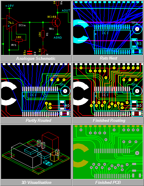
Aids such as an adaptive toolbar, pop-up context sensitive local menus (right button), quick access to recently used operations, and an integrated tutorial and practice environment, promote early learning and productivity.
The system is highly modular, and can be customised from a simple schematic entry system to a fully fledged 100% auto-routing PCB layout system with direct output to photoplotters and CNC drilling & milling machines. You need only buy the facilities required, and can upgrade as needs change.
Vutrax includes a selection of advanced routers, design checkers, automated updating of modifications on the PCB back onto the schematic (and the reverse), and numerous interfaces to simulators, photoplotters including RS274X, CNC drilling & Milling machines, and other equipment used by the PCB industry. Extensive libraries of schematic symbols and multiple forms of PCB footprint are provided.
The product includes complete context sensitive tutorials and technical documentation. If you prefer the personal approach, individually tailored training courses from elementary to advanced can be provided.
Key Features:
- Integrated Schematic Capture.
- True WYSIWYG operation throughout.
 Tutorials
integrated with the
system
in familiar 'Browser' style (Internet
connection not required) including
many practice and example
sequences.
- Design for modern PCB technology includes Surface Mount, Gluespots, Blind and Buried Vias, Microvias, Components on both sides, pick and place, etc.
- Bidirectional Modification with integrity.
- Selection of Autorouters including orthogonal, ripup and retry, and Shape Based styles.
- On-line and Off-line Design Validation.
- EMC compatibility Checking.
- Capabilities for RF and Microwave Design.
- Extensive libraries of schematic symbols and component footprints are provided. A single schematic symbol can refer to the full range of the devices' packaging options, so you can take advantage of packaging advances without the reworking of schematics. Extensive search options help you find what you need.
- A single graphics editor (with mode sensitive options) is used for library, schematic, placement and routing, greatly reducing the learning time.
- Virtually infinite Undo/Redo capability.
- Choice of Metric or Imperial basic coordinates, but accepts coordinates of either type at all times. Resolution is 0.0001" (0.1 mil) / 0.0025mm
- Mechanical Drawing, including dimensioning using the same tools. You can even mix Schematics, PCBs and mechanical in the same documents.
- Use of any Windows TrueType font, even for photoplotter output.
- Settings can be preserved on the basis of Projects, Users, or both.
Selected Specialised Utilities:
- Powerplane and Groundplane generation.
- Automatic Component Renumbering of PCBs and Schematics.
- 3D View of the PCB.
- Gluespot and Testpoint (ATE) Analysis.
- Gerber RS274X or explicit aperture Photoplot output, plus output and Decoding of this and other formats.
- CNC drilling and milling outputs in numerous formats.
- Groups of settings for Plotting, Photoplotting and CNC sets for multilayer, buried VIAs etc. can be stored for rework, modification, or imported into other projects.
- Numerous linkages to 3rd Party Software including AutoCAD (DXF), CNC, ATE, Pick & Place, stock control, logic & analogue simulation, and import of various other CAD system data. Interfaces for the Electra and Specctra advanced auto-routers are also available.
- A Bitmap Import utility suitable for line drawings, Logos, Signatures, etc.
Recommended Computer Configuration
- Recommendations Configurations
- Pentium 233 or better with RAM requirements as recommended for the operating system.
- Windows XP, Windows XP, Windows
Vista, Windows Vista, Windows 7, Windows 8 & Windows 10,
including x86 (32 bit) and X64 (64 bit) variants, plus
Windows 11 (x64 only)
Earlier versions of Windows (Windows 95 onwards) should be functional but we can no longer offer support.
A PC based Linux version is also available but is no longer being developed. See Broadband Download for Linux.
- CD-ROM or Network access to the files, 100MB of Hard
disk available,
Two button Mouse, VGA
graphics at minimum, Windows printer, ports for any
attached PCB artwork plotter.
An outline of the modules is included in the sections [Schematic Entry] onwards. If you have any questions or comments please don't hesitate to mail us below.
 For
further Information, please e-mail us here
Computamation Systems Limited.
9a Lower Way, Great Brickhill, Buckinghamshire, MK17 9AG, UK.Tel: 01525 261 381
Mobile: 07968 536 068
Fax: 0871 528 4646 (Fax calls cost 10p/min)
E-mail: sales@vutrax.co.uk
Vutrax is a registered trademark of Computamation Systems Ltd.