BULLETIN
Technical Support and the Latest Information for
VUTRAX Users
|
Issue Number 34 |
July 2006 |
- Vutrax Version 13.0a -
Vutrax 13.0a was released in April 2006 for Windows 95, 98, ME, NT 3.51, NT 4.0, 2000, XP, XP x64 and Linux operating systems.
The primary content of
this bulletin is an outline of the enhancements.
Operational details of the changes are
embedded in the installed product.
- Availability -
When available, this issue of the software can be supplied from Downloads situated on our Web site (www.vutrax.co.uk) or supplied on a CD-ROM.
Those who have subscribed
to the Support and Update
Rights Agreement can either
DOWNLOAD the
software, or if a CD-ROM is required
should
E-mail us to request your Configuration File (via email).
'Freeware' customers can update from downloaded materials
alone. The same 256 pin
limits and indefinite
use apply.
Users who have NOT subscribed to 'Support and Update Rights' and would like to know more details of the costs involved, please telephone or e-mail the Computamation office on:
- 01525 261 381 -
- sales@vutrax.co.uk -
- Vutrax 13.0a Enhancements -
General
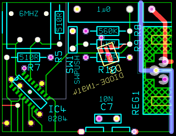
- Vutrax provides full support for turning components to any angle (0.1 degree resolution). The changes include arbitrary rotation of script, pad shapes and rounds and curves that form part of silk screen outlines and elsewhere. Device orientation is maintained through Analyse Placement, Back-Modify and Forward (Top-Down) modification.
- DRAFT supports 64 layers which can be assign in any way you please and 2047 pad shapes are now available for user definition.
- Support for multiple layer silk screen symbols.
- A graphical editor Edit Silk Shape (EDLIBSLK) is available for altering the silk outlines from existing Physical Libraries (.LIB), particularly (but not limited to) assigning meaningful layer changes.
- A new utility Create Library (CREATLIB) for generating usable physical libraries for use where only schematic and PCB artwork files are available for modification (quite a common situation when modifying old designs).
- Windows XP x64 is formally
supported, including provision of a new 'Help' Browser
that will operate in
the 32/64 bit only environment.
Database Change
The major enhancements achieved in Vutrax 13.0 are primarily concerned with functionality and were impractical without a database change.
- Pad definition or use above pad 999.
- Explicit turned pad actions are
specified in the pad
table, or degree turned pads are
used.
- Degree turned Script or Rounds are used.
- Layer
numbers over 31 are used.
- Round and Butt end are both used on a single width (making it impossible to define them unambiguously with a single width based CAPPING table)
- Vutrax 12 Artworks presented for plotting at Vutrax 13
based manufacturers.
- Vutrax 13 Artworks presented for plotting at Vutrax 12
based manufacturers who
process the artwork using the
Vutrax 12 Utility and are
presented with no warnings.
- Various comma separated forms
contain additional information about degree pad rotation
when it is used. When not used the file format is
unchanged.
- Schematics and other drawing where VTX13_12 utility presents with no warning
Forward Compatibility
Vutrax 13.0 accepts graphics files from all older version of Vutrax.All your data and libraries are forward compatible - Vutrax-13 can still read and edit files written in the 1980's!
Whatever is in a Vutrax 12 artwork is preserved in Vutrax 13 unless a new rats-nest is generated (e.g. by Top-down-Modify) when some aspects of turned components may vary.
Backward Compatibility
Vtx 12 Graphics from (Functions)

Graphics files written by Vutrax 13.0
can be converted to
Vutrax 12 readable form using
a
supplied utility. Apart from detailed format changes the
following conversions are performed and
warnings generated as necessary:-
Each warning is includes an assessment on its likely impact so that the user can decide whether the resulting file can be used or the Vutrax 13 file first needs simplifying.
Compatibility Issues
Where designs use the Vutrax 12 directive <TURN ANGLE> in the library, some problem may be experienced with compatibility of rotation where the library TURN is not positive and less that 90 degrees, or where the component is on the 'back' side.
A Rats-Nest (WIRE) option can be used to force compatible operation at the expense of some new features.
Placement (.LAY) files from Vutrax 13 may need manual modification for use in Vutrax 12 to remove any DEGTURN keywords and values).
The following however, work without
any changes:-
Draft Interactive Graphics Editor
Function Key Allocations
The general adoption of function key F5 as 'Repaint' in Windows Explorer & Internet Browsers has led us to swap the functions assigned to the F5 and F7 function keys, along with their Shift & Cntl states.
The graphics file KEYPLATE.DIA in the ...\WORK folder contains a printable function key template that fits PC keyboards with standard size Function keys arrayed in groups of 4 along to top of the keyboard. The file is standard Vutrax graphics - you can massage it and rescale it during printing to whatever you want.
Turn
Vutrax has long supported the turning of outlines (including CURVEs) by arbitrary angles with support for 45 degree turned rectangular pads. This has now been extended to provide full support for turning components to any angle (0.1 degree resolution). The changes include arbitrary rotation of script, pad shapes and rounds and curves that form part of silk screen outlines and elsewhere.
The 'size' field for Script Text, Rounds & Pad Shapes can include an additional specifier:-
D<turn angle>
where the <TURN ANGLE> can take any value from 0.0 (no effect) to 89.9 degrees in increments of 0.1 degree. Integer values (no decimal point) are accepted. Such a rotation on an object is known as a Degree Turn (DEGTURN).
Round Points maintain there radius and segment information independently of the 'Size' field, and maintain their Degree Turn (DEGTURN) separately, It can be explicitly set using a variant of the ROUND command as in:-
ROUND ... D <TURN ANGLE> ...
The command 'turn' now applies the turn angle to each of the Script, Round & Pad Shapes in the turned item so that the whole shape is changed naturally. Options are available to provide more control of the 'turn' command.
Turn ... from (Edit > Turn)

Turning Components
Turns the selected component silk screen, silk legend, component footprint and component pads by the nominated angle. The command adjusts the actual turn angle to the nearest resolution that Degree Turn (DEGTURN) permits, and adjusts the angles of any pads and rounds on the selected structure and any pads moved as part of the device.
Note: Device orientation is maintained through Analyse Placement, Back-Modify and Top-down modification.
Turn Component ... from (Place)
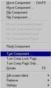
Turn Comp Lock Pads ...from (Place)
Turns the device, but does not apply changes to silk legend or component pad orientations.
Turn Comp Pads Only ...from (Place)
Turns the selected component silk legend and component pads by the nominated angle, but does not change any point coordinates.
Various 'Pick' and 'Blink' commands are also available for 'Turn' manipulation, as follows:-
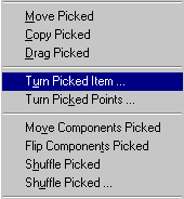
'Pick' and 'Blink' Just Variants
The 'JUST' directives can be added to a number of Pick and Blink marker setting commands to clear existing markers first. The change from Vutrax 12 is that after the command has been executed most of the 24 command styles including JUST change their prompt to the standard TOGGLE or set to ON variant as appropriate so you can add further selection and/or toggle the settings without selecting a further command.
The exception are the command forms which include a <WILDCARD NAME LIST>.
Layers and Colours
Vutrax 13 permits use of 64 user assignable layers, and provides additional controls on their use by way of display without selection and use of multiple layers in silk screen outlines.
This dialogue can be invoked by either clicking on the layers/colour bar at the bottom of the screen or by selecting: -
Show Palette from (View)
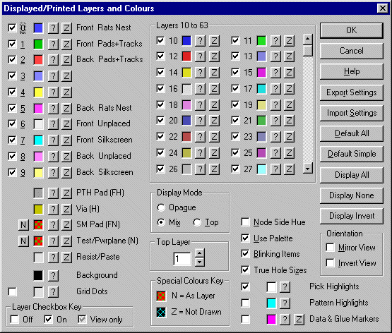
The Check boxes for each layer can now take 3 states to support a new visible (or Zilched) but not selectable feature:-
Unchecked:
Not visible nor selectable
Checked:
Visible (if not Zilched) and selectable.
Gray Checkbox:
Visible (if not zilched) but not selectable unless a Hole or Fixed Hole designated for that layer is also visible on a selectable layer.
The layer selection check box automatically updates when you explicitly select a colour, or change the layer from normal to Zilch colour or back. Normally the new selection will be what you want - if it isn't click on the check box to change it.
Also within the dialogue box
Save Colours has been renamed Export Settings
Restore Colours has been renamed Import Settings
to reflect that this feature now permanently stores the complete settings controlling how drawings are displayed by way of colours, layer selections, selectable layers etc., explicitly excluding display the area and zoom factor.(Previously only the colour selections and selected check boxes were stored in the created file).
The list of layers and colours at the bottom of the Draft screen has been re-formatted into 'decades' of layers to accommodate as many of the 64 layers as practical within the window width available.
'Show' command 'Same Colour' option
For command & macro users , the colour 'S' can be used instead of the primary colour letters to specifies the same colour as already imported as a palette or set through the dialogue box, and can be used to enable a pad or layer display without assigning one of the primary colours. Any Zilch colour is cancelled but 'NODE and FIXED NODE the same colour as tracks' is not cancelled if currently selected.
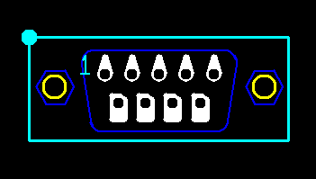
Multi-layer Silkscreen Components
Multi-layer silk shape library definitions can be specified with the additional layers fixed or changing with component side assignment.
Side Dependent Unplaced and Placed Silk Layers
Set Sides from (Place > Options)
The designation of layers as Rats Nest, Pads, Unplacement Components & Placed Components is unchanged, but an additional section of this table can be used to define pairing of layers used in silk screen outline which exchange sides if the side on which the component is mounted is changed.
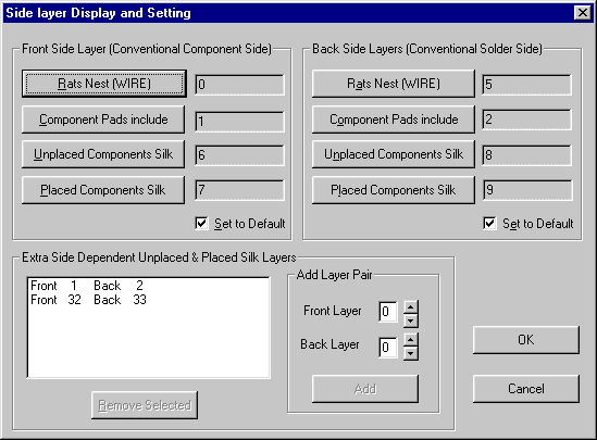
Note: This table has an equivalent that should be included is the Rats-Nest Rules (.WRL) file so that layers are initially assigned correctly in the rats nest.
Line Capping
Vutrax 12 supported Line-Capping by means of a 'Capping Table' that specified whether any particular width was to be Round or Butt-ended.
Vutrax 13 stores the selection on a per line-segment basis. The 'Capping Table' no longer exists. By default lines are Round-end as is the normal requirement, but commands are available to individually or mass-set Round or Butt-ended within Draft
Width ... from (Edit > Properties > Width)
The width absolute and incremental parameter can accept a capping directive letter before the width or immediately after the width (without a space) from one of
B Force Butt ended
R Force Round ended
U Explicitly leave line ending alone (The default)
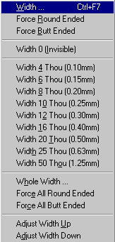
To change the line ending style of a single selected point without changing the width.
Force Round Ended from (Edit > Propertues > Width)
Force Butt Ended from (Edit > Propertues > Width)
Multiple changes for 'Boxed', 'Picked' or 'Blinked' width operations
The <FROM> and <TO> specification can take a suffix letter:-
B Select only / Set to Butt ended
R Select only / Set to Round ended
U Select either line end style (default) / Leave line end style unchanged (default)
Pad Changes
The Pad definitions table now supports 2047 pad definitions (pads 1 to 2047).
Degree Turned Pad Handling
The pad shape table defines for each pad shape what should be done about pads specified at an angle (0.1 to 89.9 degrees).
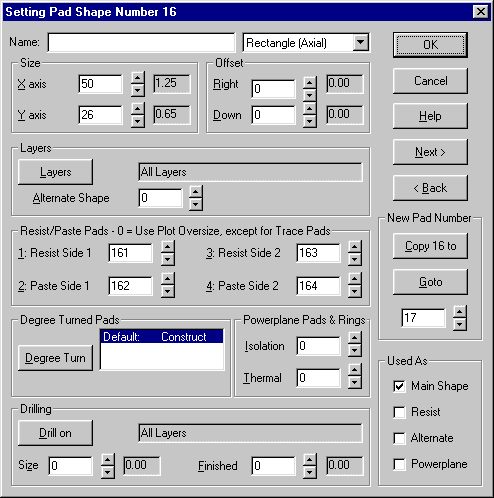
For each pad there exists a table of defining what action should be taken for each of the possible angles:-

Construct Pad Shape:-
Vutrax internally creates a TRACE shape that provides the defined shape in it's turned form. This is the default and most user will leave this as the most suitable setting.
Alternate Shape:-
Vutrax will use the nominated pad shape number (at its normal orientation) for the pad at the tabulated angle. The nominated alternate can be 0 (zero) to specify that the pad should not be plotted.
No Alternate:-
This pad at this angle is specified to be not allowed. Various parts of Vutrax complain in their appropriate ways if such a pad shape is requested.
Trace pads can now be constructed using Butt-ended lines allowing accurate and efficient construction of rectangles and sharp cornered' shapes.
Design Management
Rats Nest (Wire)
In Vutrax 12 component oriention was controlled from the library or by ad-hoc use of TURN DRAG. Some complications arise in moving designs using turned components to Vutrax 13. While PCB layouts carried into Vutrax 13 appear the same and can be manipulated without problems, use of the design modification cycles can be eased by using some new options:-
Custom ... from (Tools > Interconnect > Make Rats Nest > Extra Options)
-YD
Suppresses Degree Turns in the .LAY file and correspondingly obey library defined turns and pad substitution specified by TURN and ALTERPAD statements.
This option provides full compatibility with Layout files written by Vutrax 12 and should be used when continuing modification cycles on artworks from Vutrax 12 when the additional rotation capabilities are not required.
-YT
Library descriptions containing TURN or ALTERPAD directives are treated as defining the preferred library item from which to derive the footprint. Implied by option -YD
This option is primarily intended for use with libraries where only the TURNed component with alternate pads is properly defined.
-YW
Suppresses warnings when finding TURN or ALTERPAD directives are found in the library and are being ignored.
This option allows you to suppress the warnings without altering the libraries.
Options -YD, -YT and -YW are mutually exclusive and should not be specified together
Degree Turn in Libraries
Definition or Pad, Script and Rounds in the library can include
... D<DEGREE TURN> ...
directives. Within the SILKSHAPE definition the format accepts a specifier, immediately before W <WIDTH>,of the form
D <DEG TURN>
Device Turn in Placement (.LAY) files
The start of each device placement directive takes the form
<ORIENTATION> PLACE <DEVICE NAME>
where <ORIENTATION> takes the form
[ INV | LAT] [DEG <ANGLE>] [ QROT | HROT | TROT ]
Degree Turns can also be embedded in records of the silk legend and other text embedded in the @...@ section of the placement file. e.g.
lat deg 70.0 qrot place
DIODE-1N914 4625 775 @ 0U 1 8LD70T 225 225 ;
SCRIPT 250 300 6LD70T "DIODE-1N914" ;
GLUE 78'6 40'6 @ D3
Angles in the Kitting (.KIT) file
The 'Rot< 90 | 180 | 270>' field that may be present in Kitting (.KIT) file entries is replaced by the form:-
Rot<1..359>
or
Rot<0.1..359.9>
Design Rule Check (Desrule), Automatic Routing (Autotrak)& Rip-up & Retry Autorouting (Vuroute)
SYNONYMS Rule
You can specify items in the SILKSHAPE part of the library defintion to be on tracking layers, so it is possible to include heat sink pads and the like as part of the footprint. You can find an extreme worked example of a hatched area related to a voltage regular REG-7805 in file Sample.lib and Sample Partially Place.slk in the ..\samples folder.
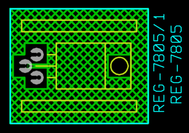
To make the design checker ignore apparent violation it may be necessary to SYNONYM the silk outline name (the library device name) with the signal that the copper represents, as in
SYNONYMS 0V REG-7805 ;
Plot
'UB', 'UU', 'U?' and 'Q1' options
The UB ... and UU options for forcing line end style based on width ranges are no longer relevant and has been discontinued. Their use generates an error diagnostic. Vutrax 13 can apply functionally identical changes to the artwork file.
The harmless U? option for checking for butt-end lines in the artwork is also redundant. This option generates a minor warning and the continues. It has no functional effect.
The long deprecated option Q1 (for compatibility with Vutrax 9) now generates an error diagnostic.
Utility
- The name of a Vutrax Artwork, Rats-Nest or
any state in-between. The artworks must
include the standard Vutrax silk screen outlines and
pin-information.
- A destination .LIB filename to store the resulting library. Do not casually overwrite any existing library.
- The width of the standard
silk box and the corner marker
size.
When SILKSHAPE is use this is assumed to by "SILKSIZE 0 0U ..."
- Optionally the size of the silk screen legend.
- Optionally (only if the above all appear) the relative position of the silk screen legend.
- -12 to edit Vutrax 12
libraries without converting
them to Vutrax 13 forms - Layer
changes are discarded.
Degree turn assignments should NOT appear and will cause problems if the Library is used in Vutrax 12. - The shape structure name is the
same
as that of the library
device.
- Point 1 is a data point identifying the line in the
.LIB
file at which the SILKSHAPE
sequence starts.
- Point 2 is a small NODE identifying the 0, 0 reference for
your device - normally 'Pin 1'.
- Point 3 is the first point of the library SILKSHAPE
which follows sequentially.
- The graphics file is selected as
THOU
or METRIC to match the most used coordinate
type in the library. Each SILKSHAPE is maintained
in whichever coordinate system it
was defined in. When the coordinate system of the
SILKSHAPE does not match that of
the graphics file then coordinate are converted to and
from the graphics using unscaled
coordinate mapping where 1 Thou = 0.025mm. This avoid
potential rounding errors but
you need to be aware of this if you a precisely
re-sizing.
- Library items without SILKSHAPE
directive are not represented in the graphics file. If
you want to build a shape for a device without one
first edit the .LIB file and in each
device you want to edit find the first 'group' or
'fixed' keyword and insert the line
SILKSHAPE 0 0 8 A
- If you add any points, script
etc. to a shape ensure that it is joined to the original
structure - e.g. Flash (Draw 0) to see
the whole outline flashing.
- You can move the whole of any
structure that you like, but do not alter the first or
second
points except for incidental changes to the layer.
- Shapes you don't want to change
can (and preferably should) be deleted - Any structure
shape with an appropriate first two points will be
re-evaluated and a new SILKSHAPE
sequence generated. Unchanged shapes will functionally
match the original but which
may be differently laid out in the .LIB file.
Support for Windows XP x64
Windows XP x64 is formally supported, including provision of a new 'Help' Browser that will operate in the 32/64 bit only environment.
To support help browsing an alternate browser is selected which runs in 32 bit mode - a later section discusses why and how you might select this browser on Windows XP.
Vutrax Shell (Vtxshell)
The banner and environment variable WINNAME identify that is is running in the 64 bit variant of Windows XP with the string
Windows XP x64
Operation with a 64 bit processor using standard Windows 95 through XP generates the standard operating system identification.
TIMESTAMP /F <FILENAME> style commands now sets the additional environment variable FSIZE to the decimal size of the nominated file.
The Linux version now supports the OPEN command. It associates the standard Vutrax files extensions with either DRAFT or SEE.
Vtxhelp - Webview & Amaya Browsers
Windows XP x64 (for 64 bit support on 64 bit processors) will not run 16 bit applications, so on this operating system Vutrax can not use 16 bit Windows application Webview. For XP x64 systems the browser Amaya is always automatically selected. For Windows XP onwards Vutrax continues to use Webview but can instructed to use Amaya by selecting
[Set Environment] from (File > Setup)
and adding the setting
set VTXAMAYA=Y
Note: This setting is ignored for Windows 95, 98, ME, NT and 2000
Amaya supports the mouse scroll wheel, is more HTML standard compliant than Webview, and can be used for web browsing. Page layout is also cosmetically different - you may or may not, prefer it.
To improve rendering performance the standard green navigation buttons are normally replaced with standard grey buttons. If this doesn't bother you and you would prefer the green buttons, select instead the following setting (which also changes the rendering in the Linux version though it is less of an issue here)
set VTXAMAYA=C
To revert to Webview either:-
Visit the same item and remove the 'Y' or 'C' and leave the box enabled (this scheme is convenient for flipping back and forth between the two browsers)
or
Remove the mention of VTXAMAYA altogether and restart Vutrax (best scheme for reverting to normal operation).
The Linux issue uses only the Amaya Browser which has been upgraded to issue 8.8 with CMSL local CGI modifications You should find the rendering a lot tidier than the previous issue.
Draft (Graphics) & See (Text) Editors
These editors now append an asterisk ('*') to the filename when changes have not been formally saved by the user. Automatic saves (usually selected to be written to an alternate name) may be lost so this does not clear the marker.
Protection against program exit or system shutdown without saving remains.
Vutrax System Menu Window
Previously the Vutrax Menu sytem window preserved it's position only in the Maximized state so could not be permanently reduced in size. If you now select Normal size you can adjust the window size down to 2 lines high (enough for error and status messages) and can be reduced in width to only just fit in the menu bar. Such settings are new preserved.
New Utility - Creating a Library from Artwork (CREATELIB)
This generates a physical library (.LIB) for the devices used in a properly formed Vutrax PCB layout file.
It is designed to be used in conjunction with an existing schematic or the output of:-
Make Device List or Make Pin List from (Tool > post-processing)
to permit modification work on designs for which only the final artwork (and possibly schematics or pin list) still exist.
Create Library from Tools > Post-processing

However started the features
requires just two parameters:-
Each device found generates a library name based on the silk outline structure name and assigns the pins and groups as the pin-information points indicate.
Multiple instances of the same device appear just once in the library, but devices using the value style (embedding a '#' in the name) produce a devname library for each distinct value. If you subsequently want to add or change a value you can either duplicate one of the exsting values and assigned the new value, or derive a devvalue style library item, being careful that some of the values are not physically different as is common with capacitors.
The silk outline is analysed and encoded in library format - in some circumstances it may be convenient to analyse an artwork and then Copy & Paste such definitions into existing libraries
The pad shapes in the artwork are translated to PADSHAPE directives in the library.
No attempt is made to interpret any SIDE, or SILKSIDE directive which should appear in the Rats-Nest Rules (.WRL). The Physical Library does not embed any Script font settings so you may wish to import these later from the original artwork.
New Utility - Graphical Edit of Library Silk Directives (EDLIBSLK)
This utility is designed to help you make use of the new multi-layer features available for silk screens by editing changes to silk shapes in existing .LIB files in the graphical domain. The procedure is as follows:-
Archive your .LIB files first
Make safe copies of your existing .LIB files to guard against loss in the case of your own or system errors, and to retain a set of libraries for use with Vutrax 12. Layer selection with SILKSHAPE directives is not back-compatible with Vutrax 12, but if you leave the layers as standard then this tools leaves libraries compatible with Vutrax 12.
Edit Silk Shape from (Tools > Library)
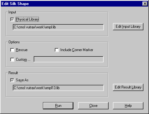
For safety the menu system requires selection of the destination filename. You can opt to write the result to a different file or back into the original file (generating a .BAK file of the original)
Check box
Include Corner Marker (Option
-Z) specifies handling of the single SILKSIZE
directive per library is optional. This field includes:-
If you include such processing then Edit Silk Library assigns it's own default values to unsupplied fields and these will become the libraries defaults unless you explicitly adjust them or remove the whole silk item.
Custom option can include
DRAFT Edit the file generated
Edit Silk Library (EDLIBSLK) reads the .LIB file and generates a graphics file (normally EDLIBSLK!.LOG in the current folder) that contains all the graphical shapes laid out in an array. DRAFT should start automatically to enable you to edit this file
The shapes are identified as
follows:-
When you are happy with your changes [Exit] from DRAFT saving changes.
Analysis and output
Edit Silk Library will ask you to confirm that the update should go ahead.
If you say NO or something goes wrong during analysis you can still analyse the graphics using the -RESCUE option.
You can check the results are in a .LIB file by applying Edit Silk Library to the file but declining to update when you exit DRAFT.
Computamation Systems
Ltd.
Tel: +44 (0)1525 261 381
e-mail:
sales@vutrax.co.uk
Vutrax is a registered trademark of Computamation Systems Ltd.
